Gear up - Making gears! by David Matthews

1. Determine the total number of teeth, radius to the inside of the teeth and radius to the inside of the teeth. ​(Determine if you have rounded or pointed teeth to your gears.) If you have rounded teeth add the rounded size outer diameter and subtract it from the inner diameter.) 

2. Create cross hair construction lines to find the center point of the gear. ​

1.gear.JPG

3. Draw two circles that correspond to the inside and outside radius of the gear teeth. ​

2.gear.JPG

4. ​Draw a single line from the center point to of the gear to the outer edge of the outside circle. 

5. ​Put the line created in the step above on a unique layer. 

6. Lock the layer of the cross-hairs and circles. ​

7. Using the command ArrayPolar rotate twice the number of lines than teeth in the gear. ​

3.gear.JPG

8. Lock the layer of arrayed lines. ​

9. On a unique layer draw one tooth of the gear between three of the lines.​ (For rounded teeth create three teeth and fillet the edges of the teeth.)

4.gear.JPG
5.gear.JPG
6.gear.JPG

10. Trim the the three teeth to one tooth.

11. ​Lock all layers except the layer of the teeth.

12. Select all of the teeth and using the join tool make them a single line/curve.​

7.gear.JPG

12. Using the arraypolar command create the number of teeth in your gear. ​

13. Using the menu command Solid--> Extrude Planar Curve --> Straight  Extrude the gear to the correct thickness/height. 

8.gear.JPG

14. Add holes, depressions, or other ​characteristics to your gears.

Making springs from sweeping a helix curve by David Matthews

​These are basic instructions for making a spring of similar shape.

1. Determine the height, radius, and the number of rotations in the spring. ​The number of rotations is total number of times the wire makes a full circle. 

2. ​Draw a line that corresponds to the height of the spring. 

1.spring.JPG

​3. Enter the "helix" command. 

4. Create the helix around a curve.

5. Enter the number of turns. ​ (In the image below you see two helix with a 6" radius, one with 12 turns and one with 6 turns.)

6. Enter or draw the radius. ​

2.spring.JPG

​7. If you need to add a top loop or extra length to the spring add the follow steps. 

8. ​Add extra lines and make sure they begin at the end point of the heilix by using the end object snap. 

​9. Connect ALL of the curve/line segments with the join tool. 

3.spring.JPG

10. Turn on the Edit points and refine the shape of the wire by removing all sharp corners and edges. (Rotate and view the wire form in different views to make sure you edit out all of the kinks and create a smooth, accurate shape.)​  In the above image the helix on the right has sharp edges and will not make a smooth spring. The helix on the left has been smoothed out by transforming the lines from sharp corners to smooth curves.  This take a bit of good craft to make sure that all of the lines are now smooth working in all views.

11. ​Create a cross section of the spring. (This is typically a small circle.)

4.spring.JPG

12. Place the center of the circle perpendicular to one of the end point of the wire spring.​

13. Using the sweep 1 tool create sweep the circle along the wire path. (​Select the Untrimmed Miters option;) 

5.spring.JPG

​14. Cap the ends and make the shape a solid. 

Nut and Bolts by David Matthews

To create nut, bolts, and other similar models you can download cad models from the internet. ​

Go to:​ http://www.mcmaster.com

​Measure you nut, bolt, screw, etc... and find the closest one in the inventory.

​Click on the part number, then click on CAD.

​I was successful using the 3-d Solid works file format. Other formats may also work. 

Download, save and open the file in rhino. You should have a nicely modeled fastener!​

​Copy and paste the modeled object into the files you need the part. You can use the part as a whole, trim the part, or use the part to make a hole to receive he bolt if you use the Bolean tool. ​

For  full list of file types that can be imported to Rhino go to:​

http://www.rhino3d.com/4/help/fileio/file_formats.htm

Modeling Assignment 5 by David Matthews

This assignment is to provide an introduction on how to use tools together to make complex solid shapes. ​

Download the Rhino Training Guides One and Two from:​

http://download.rhino3d.com/download.asp?id=Rhino4Training​

​From Training Guide One complete the following:

  • Editing Solds (p. 166-168) stop at the end of page 168. ​
  • Exercise 65 Creating a Toy Hammer (p. 199-207)

Upload the screen shots to blackboard.​

Sweep 2 by David Matthews

Create a cross section of seating. (fixed sectional)​

Create a curved line sweep the sofa section shape.​

Align the section shape of the seating perpendicular to the curved line. ​(Use the perpendicular to curve line tool.) Move the section shape to the end point of the curve line. Then rotate the section shape to match the curved line. 

Sweep the section along the edge of the curved line. ​

Cap the end of the curved seating. ​

Link to large image.​

sweep seating.JPG

Fillet Surface and Object by David Matthews

​Create two surfaces that meet at 90 deg. along an edge. 

Create three copies of the surfaces. ​

​Using the fillet and chamfer tools create a fillet edge, chamfer edge, and variable fillet edge. 

Create a block with notch and cylinder. (make sure that the cylinder is in the center of the top of the block).​

Fillet the inside and outside edges of the object. Control the dimensions so the fillet command works correctly. ​

Link to large image. ​

fillet.JPG

Basid NURBS (non uniform rational b splines) by David Matthews

Loft (making a surface from a set of curves (lines)

  • Create three b-spline curves and stack them on top of each other (similar shape)
  • Using the loft tool ​create a lofted surface. 
  • ​Turn on the control points and edit the shape. 
  • ​Offset the surface (surface -- > offset surface) 
  • ​select solid (in the command bar)
  •  ​enter the depth dimension to offset​
  • change the direction if necessary ​
  • select ​loose (in the command bar)

Full Size Image

​

Trim, Split, Holes and Wire Cut by David Matthews

​Trimming and Splitting Objects

Trimming Lines​

  • Create four lines that overlap in a rectangular shape.
  • Use the trim tool to cut off the extended lines.​

Splitting Planes​

  • Convert the rectangular shape to a surface
  • Make a round curve in the surface​
  • Use the Split command to subtract the circle fro the rectangular shape (Edit-->Split)​
  • ​Delete the circle surface to reveal the rectangular shape with the round hole. 
  • Transform the surface to a solid (Solid-->Extrude Surface-->Straight)

Making Holes​

  • ​Make a 3D solid by going selecting your surface and (Solid-->Extrude Surface--> Straight) 
  • ​Make a closed curve in the view corresponding to the direction and location you want to make a hole in your shape. (Right Side)
  • ​Using the Make Hole tool make a hole in your object 

Wire Cut​

  • Create two lines in the top view to trim part of your object
  • Move one line above the object​
  • Trim the object with the two lines using the Wire Cut tool​
  • Make one cut clear through the object​
  • Make one cut partially trough the object​

​Full Size Image

​

Boolean by David Matthews

The Boolean tool ​allows you to subtract solids from each other. This is a powerful tool that allows the creation of subtractive spatial qualities to your models. 

Difference - Allows you to subtract one solid shape from another solid shape.  

  • Create two solids that intersect each other.
  • In the Solids ​Tool Palette select the "bollean difference" tool. 
  • Click on the object you want to keep.​
  • Then select the object you want to subtract. ​

Inter​section -- Derives the shape from the common space of two intersecting objects.

  • ​Create two objects that interstect each other.
  • In the Solids Tool Palette select the "boolean intersection" tool​
  • Click select the two objects ​

​Full Size Image

​

Setting Up the Modeling Environment by David Matthews

In Rhino, and other modeling and CAD programs, you draw in full scale. Unlike your drafting boards you do not use a scale when setting up your drawings. When re are ready to print you select the scale for the correct output. ​

  • When entering size information in Rhino use the full dimension
  • ​When you print information you can set the correct scale for accurate drawings

Review Chapter 8: Modeling Aids in Lynda.com Rhino 4 training.​

Turn On Osnap and Distance in Cursor - Go to File --> Document Properties, Select Modeling Aids --> Cursor ToolTips, Enable cursor tooltips, Osnap, and Distance. ​This will allow you to see the distances and snaps next to your cursor while you make shapes.
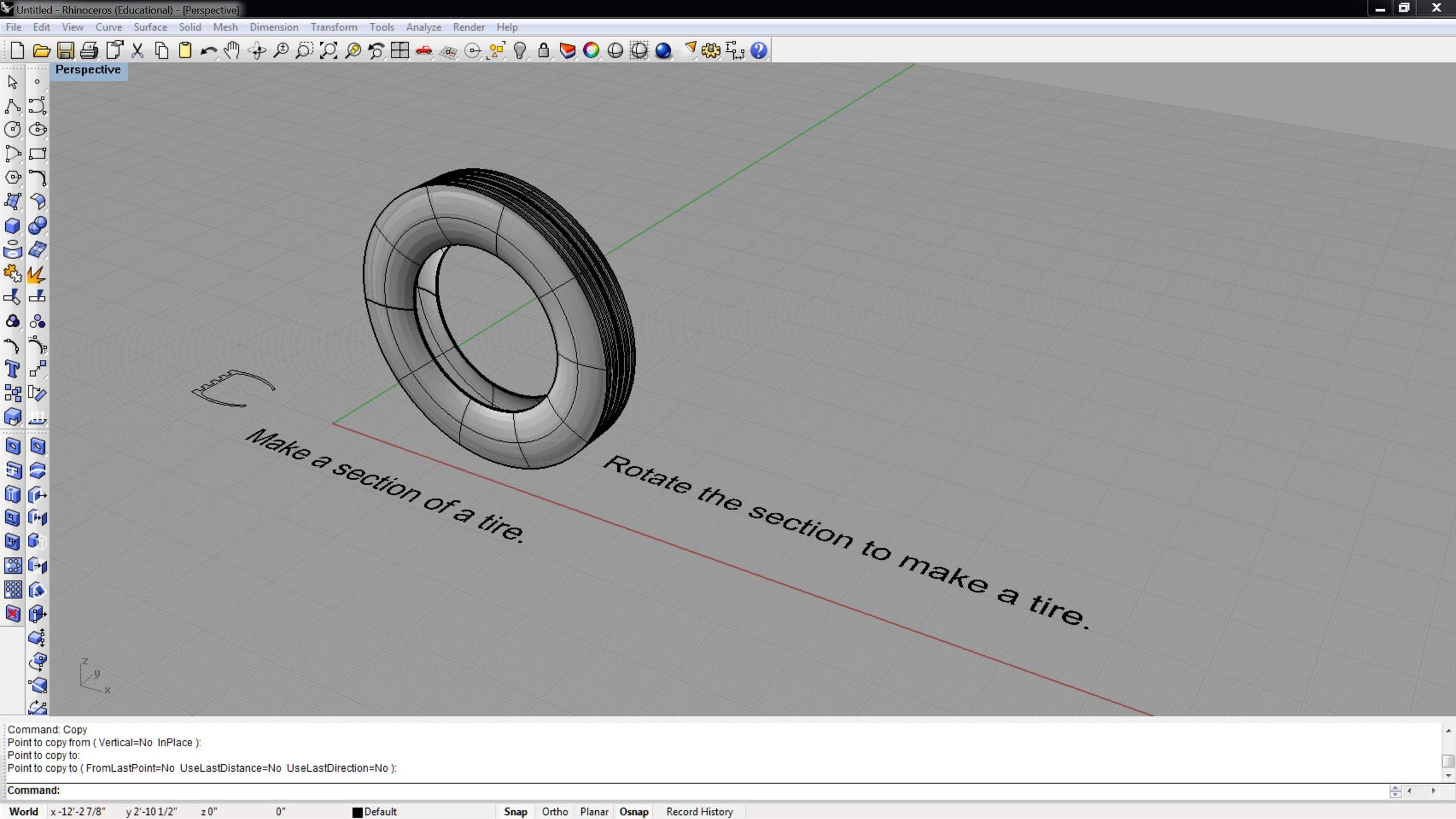
On/Off​ - The tools below can be turned on and off. Make sure you know how to turn them on or off.  Check the lowest bar with information at the bottom of the Rhino screen. You will see "Snap, Ortho, Planar, and Osnap (object snap) . When you see [ Snap | Ortho | Planar | Osnap ]  ​-- the bold Snap and Osnap are On and the Ortho and Planar are turned Off. 

Grid​ - Set the size and units for your grids. (Think of your grids similar to drawing with an underlay of graph paper.) You can change the size of the grid at any time in your project. I start by thinking of the size of graph paper I need for my project. 

  • Under file select Document Properties
  • Select Grid​ Properties 
  • Set the Grid Extents to be the overall size of your grid layout (just larger than your overall size of your design project)​
  • Set the Minor Grid lines to 1/2 your smallest tolerance, (for example if you are drawing to the nearest inch set your Minor grid line to .5" (or 1/2 inch) ​
  • Set the ​Major lines every times it take to equal one foot. If you set the minor grid lines above to .5" then it would take 24 . 5 inch minor grid lines to make 1 ft major grid lines. If you set your minor grid lines to 1" then you would have 12 minor grid lines to have 1 ft. major grid lines.   

This setup is very important. You will want to coordinate your Gird and your grid snap. ​

  • If you are unsure of what to set your Grid use .5 inches for your minor grid and 24 for your major grid. This will make a grid with 1/2 inch minor line and 1 foot major lines. 
  • You can always change your grid later if needed. ​

Grid Snap​ - Grid snap allows your cursor to "snap" or lock to your grid above when making shape in Rhino. Using grid snaps if VERY important for accurate drawings. If you set your grid snap to 1" then your cursor will draw to 1" sizes.  With a grid snap of 1" you can make a line 12" long, but not 12.5 inches long. 

  • Under file select Document Properties
  • Select Grid​ Properties 
  • Set your Grid snap to twice your minor grid snap. ​

Object Snap​ - The object snap tool allow your cursor to easily find endpoints, intersection, center points, tangents. etc... This is very important setting to have accurate models.  

  • At the bottom of the Rhino screen click on the Onsap 

Ortho​ - Make your cursor draw at 90 degree angles. This is a great tool when you want to move things in 90 degree relationship to each other or 

Layers​ - Layers are used to organize your modeling information. 

  • Create a construction lines layer. Use this layer to create lines used to  make objects for your models. Think of these lines like your construction lines for drafting on paper to fine center points. 

Full Size Image​

​

Fillet (soften edges) by David Matthews

Do you need to soften the edges of object? Rhino can provide ​a fantastic array of tools to soften sharp edges. 

Fillet on Surfaces​ -- create two surfaces at 90deg angels with adjoining edges. 

  • ​Open the surface tools and select "Fillet Surface" 
  • Select and use the "​Chamfer Surface" tool
  • ​Select the "Variable Radius Fillet Surface" -- use the trim tool to complete the operation.

Create an object with a notch, curve, and nob. ​

  • ​Use the Fillet Surface tool to join the nob to the top of the shape. (Type fillet in the command line and you will see all of the fillet commands.)
  • Use the Fillet Edge too to round inside and outside edges. ​

Revolve 1 by David Matthews

​Using the revolve tool you can make items similar to those on a lathe, think baseball bat, chair l leg, tire, or vase.

​Make 1/2 section of a vase.

Revolve the curve in the shape of a vase. ​

Edit the shape of the vase into the shape of a pitcher with a spout.​

Make the surface into a solid with the offset tool.​

​*For bonus add a handle. ​

​Link to full size image.

revolve.1.JPG

Sweeps 1 by David Matthews

  • ​Create a circle and rectangle to sweep a shape along. (You can think of the circle as circular seating and the rectangle as a picture frame.)
  • Create a surface in the form of the section shape​. 
  • Move the surface section shape perpendicular to the line. Join the points to follow the rail.  ​

Using the Sweep 1 Rail Options​

  • Select the Sweep 1 Rail Tools in the Surface Tools
  • ​Click on the Rail (curve/line)
  • Click on the section shape. ​Press enter.
  • The dialog box with options will appear. ​
  • ​Under style Select Freeform 
  • Under Cross-section curve option select "Do not simplify"
  • Use the preview button to test.​
  • ​Select OK to complete the operation.

Link to large image. ​

sweep closed.JPG

Transformations (Basic) by David Matthews

​Move - Make a basic rectangular object with a notch and using the Move command change the location of the object in the modeling space. 

Copy​ - Using the Copy command or tool make multiple copies of your object.

Rotate​ - Using the Rotate command or tool revolve your object in top view.  Then make a copy of the rotated object and rotate it in the side or front view to position it on o corner.

​Scale - Use the Scale command to tool to make the object twice and 1/2 the original size. 

​Mirror - Use the mirror tool to position an identical copy of the object next to itself. 

Full Size Image​

​

Basic Shapes by David Matthews

​Points -- for reference and construction of shapes

Curves (lines) - poly curves - multiple curves "lines" joined together

  • ​open curves 
  • closed curves - Shapes such as circles, ovals, rectangles, etc.. and free form closed shapes.
  • (use the f10 key or select ​"control points on" to edit a curve
  • b-spline curves (controls on the outside of the shape)  better for 3-d and bezier curves  (controls on the line) 

Surfaces  (planes) - and Poly Surfaces - multiple surfaces joined together that remain a plane​

  • ​closed and planer curves (lines), 
  • they can be shapes such as circles, rectangles, ovals, etc... or complex forms, but they are filled​
  • "surface to planer curve" tool (in the surface tool bar) transforms closed poly curves to a surface​

Solids ​

  • open solids (like looking into an open box and have no volume) 
  • transform an closed curve to a open solid by ​ selective surface --> extrude curve --> straight 
  • closed solids (​a closed box with measurable volume.) a "real world" shape
  • "solid-->extrude planer curve--> straight" transforms a surface to a closed solid 

Full Size Image​

​